26 October 2012

Managing Detail in Revit Families

In my previous post Too much Detail: why is my computer so slow? I explored the problems of over-modelling in Revit. In this post I describe an approach to creating Revit families that deals with this problem.

The original authors of Revit actually recognised the problem of over-modelling and provide a method to deal with it: Detail Level settings of Fine, Medium & Coarse. Yet these are rarely used to their full advantage. 

REPRESENTATION LEVEL

One way to conceptualize how to use Detail Levels is to think of models as possessing a representation based on their level of detail:

2S  - Symbolic or simplified 2D. Plan 2D representation only, using Symbolic lines
           and Masking regions. Only appears in plans.
2D  - Full 2D. Plan 2D representation only, using Models lines.
            Appears in plans and 3D views.
3S  - Simplified 3D. Block 3D model. Used in plans and elevations.

3D  - Full 3D. Realistically modelled. Used in 3D views only.


You model to one of those representation levels, and assign elements to the appropriate Detail Level  (Coarse, Medium or Fine) when making the families. Anyone can then control which one will be visible in a view within a project by selecting the appropriate Detail Level (refer red squares in image above).

To create this level of control select elements in the family file and change Family Element Visibility Settings.


How might you use this on a project?
By setting the Detail Level to Fine in a rendered 3D view you get it in glorious detail (as 3D rep), set to Medium in a room elevation and you see a simplified representation (as 3S rep), set to Course in an overall 3D view and the location of furniture is shown (as 2D rep) but doesn't clutter the architecture.

FAMILY CREATION

Now you could create different family files for each representation of the same object. But if more than one family for the same thing is used in a project you will start to get management complexity I'm sure you could do without. Someone needs to make sure all versions are captured in schedules. If it is required to change the object, either its appearance or scheduled parameters, someone has to ensure all versions get changed. Both in the project and within the family library.

But there is no reason why there can't be ALL representations in the same family file. If Detail Level settings are created correctly only one representation will be visible at a time once the family is in a project.
Although putting them all in one file can make creating families a little more complex, my view is every extra  minute spent on making a family better saves every person (and there may be many) who uses that family at least 5 minutes.
If this process is built into office practice it becomes less of a chore (as there is a clear process to follow), and leads to other benefits:
  • If it is mandated families are always initially modelled as 3S Rep the temptation by anyone to try and create a realistic representation is removed. It also drastically shortens the time to get a usable family.
  • Family templates can be created that have a parametric box already modelled, along with other parameters for scheduling. A new family can be instantly created by simply saving the template, unchanged, under a new name. It can then be placed in the project straight away, being visible both in drawings and schedules. When there is more time, or the office family maker gets to it, it can be updated with a more detailed family.
  • Poorly modelled manufacturers content can be used without all the editing usually required to make them useful. Open the manufacturers family, make sure everything is on a subcategory (i.e. not 'none'). Put all elements on to Fine Detail Level. Then copy and paste them into a family containing a 3S rep. Obviously this won't work for manufacturers families that are parametric, but most are not (one of the reasons they are poorly modelled). And generally for a 3D rep you want a realistic model, not necessarily an absolutely dimensionally correct model.

WORKING IN THE FAMILY FILE

But how do you create two models in the same file?
Although you can set the Detail Level of views in the family editor, hidden elements are made half tone rather than invisible. A way around this is to use subcategories. These can be made invisible in family editor views.

Subcategories for representation levels:

2S  -  Plan Rep
2D  -  2D Rep
3S   -  3S Rep
3D  -  descriptor subcategory (e.g. Chairs).

All elements must be on a subcategory, never on None (which is same as Category). If you turn off a Category in a view Revit turns all subcategories off as well.
I use descriptor subcategories for 3D rep because I might want to assign materials via subcategories. 3S rep doesn't usually require a material as it is not used in coloured views, but in elevations & sections. However, you can still assign a material to the 3S rep elements by assigning its material to a material parameter.

You may come up with other subcategories. The point is every element needs to be on consistent  subcategories reflecting their representation level. 

To manage subcategory visibility create views in your family file for each representation level. I have done it to my family templates so they are always available when I make a new family.


There is further control via Family Element Visibility Settings. You can change which view type an element will be visible in. But only up to a point, everything but Symbolic lines and Masking regions are always visible in 3D views.
Note also that objects not exactly parallel to an elevation or section will display as if they are in a 3D view,  Left/Right and Front/Back settings are ignored.

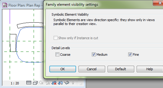
Family Element Visibility Settings for 2S elements.
(note only Detail Levels are available for Symbolic lines and Masking regions)
In this example the chair doesn't appear at all in plan views set to Coarse Detail Level.


Family Element Visibility Settings for 2D elements.
In this example a 2D representation only appear in 3D views set to Coarse Detail Level.


Family Element Visibility Settings for 3S elements.
In this example 3S rep elements only appear in elevations, sections & 3D views set to Medium Detail Level. Symbolic Lines (2S rep) are used in plan views so you don't want 3D elements to be visible in plans.
Family Element Visibility Settings for 3D elements.
In this example 3D rep elements only appear in 3D views set to Fine Detail Level.
They don't appear at all in elevations or sections.

If the realistic view is simple, use the same elements for both 3S and 3D rep.
One element can appear as both 3S and 3D rep by ticking both Medium and Fine in its Family Element Visibility Settings, and making sure Front/Back and Left/Right are also ticked.

A word about nested families.
If you set any of the Family Element Visibility Settings to elements within the nested family those elements won't appear in your family views when you place the nested family. For example if an element in a nested family has display in Plan/RCP unticked, you won't be able to see it in any plan views, which can make it nearly impossible to place it. Also if any of the Coarse, Medium or Fine settings are unticked you won't be able to use the nested family for both 3S and 3D representations in your family.
Apply any Family Element Visibility Settings to the whole nested family after it has been placed.


So there you have it. It may appear a bit complicated at first, but once you get into the habit of making families this way it is pretty straight forward. Good family templates takes a lot of the work out of it.
And you end up with highly flexible families, so people can spend more time on the project and less time making families. Or as I think of it, more time to concentrate on the architecture (or engineering).

19 October 2012

Too much Detail: Why is my computer so slow?

As BIM gets used on larger projects one on the most common complaints is how slow, and hence frustrating, working in Revit becomes. Using a more powerful computer only helps up to a point. There are metrics on what specifications a computer should have (which I won't go into in this post), but even an adequate computer won't make working on a large project the pleasure it should be.
Many people blame large file sizes, after all Revit project files of 400Mb are not uncommon.
Those that still think the CAD way believe that splitting a project into a number of linked files will solve the problem.
But if  Revit is to do all the things BIM is useful for, everything needs to be instantly accessible. Therefore  everything has to be in one file, or if in several linked files all those files need to be loaded in to your computer at once.
The reality is file size in itself, whilst an indicator of underlying problems, doesn't have a huge impact on working in Revit. The worst it does is slow down opening and saving the project file (which can still be a pain).
A greater culprit is graphic complexity, or geometric density. The more 'stuff' Revit has to deal with the longer it takes to do anything. Geometric density effects Revit in two ways: view regeneration and constraint calculations.

SLOW VIEW REGENERATION

The slowing of view regeneration is caused by the complexity of calculating hidden line removal.
I can appreciate this because back in the late 1980's, when AutoDesk released AutoShade, it would take 36 hours to do a hidden line image of a pretty simple office building. Which was longer than it took to manually trim out the hidden lines.
You may notice that software that is faster than Revit at showing 3D, like Navisworks, always uses a shaded view, no lines. In fact you can speed up 3D views in Revit by using Shaded visual style with Show Edges unticked. Try it on a large project.

When I say 'stuff', I mean detail. Every extra line that has to be calculated adds to the load.
The company logo on the Blanco cooktop family adds 136 lines that Revit has to deal with. And Revit doesn't know it is just a logo and not important.


Besides the number of lines, curves also present a calculation challenge. The line Revit draws to represent the edge of a curved surface is not based on a fixed location. Its location has to be calculated based on the angle you are viewing it from. The more curved surfaces, the longer Revit takes.

SLOW EDITING

Everything is connected in Revit, the more complex the things the object you are working on is connected to, the longer Revit takes. I had a situation where it was taking just under a minute to draw a wall in a car park. We racked our brains, ransacked google, but to no avail. Then we noticed it took no time at all to draw the same wall outside the car park floor. After some help from AutoDesk we worked out it was the Room placed in the car park that caused the problem. The car park floor was large with complex edges, and had a single Room element placed in it. Whenever a new wall was placed Revit was recalculating the Room area, (and whatever else it calculates), causing the delay. This is an extreme example, but the lesson is Revit does a lot of calculating on the fly. And although this may not be noticeable on smaller projects, it become significantly noticeable on large projects that are over-modelled.

OVER-MODELLING

I see this all the time. From the mechanical drafter creating photo-realistic fan units no-one will ever see, the new Revit user modelling a walking stick to place in a hospital project, to every family I have ever looked at provided by a manufacturer (a sink that included the bolts, wing nuts and brackets to install it is my favourite). And not just families. Existing conditions that are to be demolished modelled as if they are going to be rendered, curtain wall mullions modelled to shop drawing detail standard. The list goes on.

Here is an example of a chair in an elevation view. The simplified version shows the geometric extents of the chair without all complexity that the realistic model shows. To represent how many extra lines there are I printed both to separate PDF files. The realistic model file was 2.7 times the size of the simplified model file. When there are 10 chairs it goes to 4.5 times larger, and the time to process the realistic model file was noticeably longer.

Why do people do it?
Why do all that work when it will never be seen in any of the 1:50 to 1:200 scale drawings they appear? It wasn't such a problem with CAD, why is it a problem with BIM?
Because they can.
Revit has the tools to do exquisitely realistic modelling. And they are not that hard to use. Learners are the worst culprits. They think they are doing a good job (and they are if the task is to produce photo-realistic renders), but are completely unaware of the consequences. Other culprits are contracting BIM 'experts' who don't stick around to see the consequences of their work,  design architects who rely on photo-realistic images because they lack the imagination to visualise their design, and those who don't use the software but direct those who do, like project architects and directors.

I really see this issue as one of the biggest facing BIM use at the moment. Hopefully in the future as people become more familiar with BIM and computers get more powerful it will diminish. But for now it can't be ignored.

HOW TO AVOID OVER-MODELLING

The first step is to define the scale everyone needs to model to.
It is a simple metric that is easy to imagine and test. For example specify that only elements and detail that can be seen on a 1:100 drawing be modelled. It is easy to calculate the size of the smallest elements that can be modelled. Assuming a 0.25mm line thickness is used, anything smaller than 25mm will appear as a single thick line on a 1:100 drawing.
Specifying 1:50 (which is probably more realistic), anything smaller than 12.5mm will appear as a single line.

There is little point modelling to suit construction details. It is not possible to produce readable detail drawings from a realistic model. Things are too close together.
Flashing is a typical example. Steel flashing is 0.6mm thick. On a 1:5 drawing that is 0.12mm. By convention flashing is drawn using a thick pen, say 0.5mm, 4 times thicker than the flashing. And flashing is placed between, or on, other elements along at least one edge. Add in the pen thickness for those other elements and the full extent of the flashing is no longer visible on the drawing, there is just one thick blob.
Construction details have to be 'faked', things drawn further apart than they are so they are readable on a drawing.


SUGGESTED WORK PRACTICES:
  • If it is intended the model you are working in will be used for documentation treat it as if you are documenting, even if at schematic design stage. Only model sufficiently for documentation. (Depending how clean the design process was, sometimes it is better to discard a schematic design model and start a new one)
  • Keep in mind the fact that high levels of detail are only ever required for parts of the project, not everything in the project. An external view doesn't need the inside to be detailed, a view of one room doesn't require every instance of furniture in that room to be highly detailed across the whole project, a window sill detail is of only one window, every window doesn't require that level of detail.
  • If additional detail is required for a particular part treat it as a separate task, don't alter your main model. Create new views rather than edit existing views, place one off families rather than replace an existing one with a more detailed one, create new easily identifiable materials, etc. Then these can be deleted from the project when no longer required, and removed when providing to other consultants (who also struggle with your huge files).
  • Don't try and put everything into your project files. Consider making copies of the project file if radical changes are required to achieve a one off deliverable (e.g. an alternative design for discussion). Using Design Options is not always the most efficient path.
  • Using different families of the same thing to show different levels of detail isn't good practice. Schedules won't be correct, counting numbers becomes complicated.
  • Swapping out families is also not good practice. Unless carefully controlled parameters can be lost or altered, dimensions deleted and schedules completely messed up.
  • If you want to use this method do it in reverse -  make a copy of the BIM project for rendering, swap out families ONLY in this copy.
  • If Detail Levels aren't adequate use custom shared parameters and filters to control visibility in individual views. But be careful you don't make it so complex others receiving your model (or others working on it in your office) don't understand what you have done.

MODELLING TIPS:
  • make use of Fine; Medium; Coarse Detail Level settings in families.
  • simplify shapes; avoid curves. Particularly rounded corners and edges you won't see in a drawing.
  • turn off visibility of model objects in plan and use Symbolic lines (2D lines) and Masking Regions. But don't use symbolic lines in elevation. They won't be visible in section and elevation views that are not exactly perpendicular to those lines. Use Model lines (3D lines) instead.
  • use Model lines (3D lines) for very thin objects (e.g. wire shelf) and joints (e.g. where drawers, cupboard doors meet).
  • use fill patterns instead of modelling (e.g. meshes).
  • keep it simple. Model what everyone needs to know, not what the object looks like.   


Ultimately it comes down to training and oversight. Everyone working on your project must be aware of the consequences of over-modelling, and be familiar with the methods to avoid it.

Next post I'll offer a strategy for creating families suitable for both realistic views and documentation drawings.

12 October 2012

Which direction is Depth?

Using family components from different sources is always a pain. Not just because some are made so badly, but because everyone seems to create them differently. One such point of difference is names used for  dimension directions.
In English I count 7 different ways to describe linear dimension directions:
  • breadth
  • depth
  • height
  • length
  • long
  • thickness
  • width
  • But we only need to describe 3 directions, sometimes 4 if we want to include a material thickness.

    Until BIM it didn't really matter. We used context to decide, usually the context of convention. But in BIM a lot of this context is lost. Schedules is an obvious example. For a start if there is no consistency you end up with 7 columns instead of 3. And the height of one component may be the same direction as the depth of another.
    Another context lost is the region, country, and/or industry. Components are available world wide over the Internet. The convention in one region, or industry in one region, may be the opposite of another.

    When I bring this problem up, no-one is interested. I haven't found a standard that addresses it (AutoDesk and ANZRS are silent). People say it doesn't matter. And it doesn't. It doesn't matter which definitions are used. What does  matter is that the SAME definitions are used.  And the most effective way to do this is to come up with simple rules that can be applied in any situation.  That shouldn't be too hard. Or is it?

    THE PROBLEM

    The basis of the problem is, as I mentioned, humans understand direction names by context. Ignoring any particular industry conventions, the two common types of context are proportional and orientation.
    Proportional is when you define the longest dimension as length, next longest width, smallest depth. This the way most people normally think.
    Orientation is when you define each direction by its orientation in respect to a reference direction. This could be the person looking at it (height is up/down), an absolution reference plane like the ground (height is forward/back), or a coordinate system (height is Z axis).
    There is a very good investigation of this in the NatSPEC BIM Portal, under Workshop, Describing the dimensions of BIM objects.

    SUGGESTION 1

    Neil Greenstreet of NatSPEC, who authored Describing the dimensions of BIM objects, came up with a schema that tried to address how most people treat direction naming. A full description is on the NatSPEC BIM Portal, but in essence it is:

    For unfixed materials, use a proportion-based schema:
    1. Use length, width and depth for cuboidal forms.
    2. Use length, width and thickness for linear or planar forms.

    For installed (or ready to install) elements, use a mixed orientation-based/proportion-based
    schema:
    1. Use height, width and depth for cuboidal forms.
    2. Use height, length and thickness for vertical planar forms.
    3. Use width, length and thickness for horizontal planar forms.
    Note: The difference between cuboidal forms and planar forms would need to be defined by
    an agreed aspect ratio.

    My feeling is this is too complicated. There are too many different rules. Also a proportion based schema will never work where components are parameter driven. You can't change the label of a parameter when its value becomes the second longest instead of the longest.

    SUGGESTION 2

    Thinking about this problem I believe the best approach is to use the idea of orientation only. The orientation that works in the majority of situations is based on standing in front of the object.  You need no other context than the object and your (imagined) self.
    This rule works for most objects:

    DEPTH   =  FRONT to REAR
    WIDTH   =  LEFT to RIGHT
    HEIGHT  =  BOTTOM to TOP

    An alternative could be:

    WIDTH     =  FRONT to REAR
    LENGTH   =  LEFT to RIGHT
    HEIGHT    =  BOTTOM to TOP

    It doesn't really make much difference, but I stuck with the first rule as Revit uses these names in the casework template.

    But some objects don't fit this rule. Objects like beams, ducts, floors. Although hard to precisely define, these types of objects could be described as having a horizontal orientation - dimensions parallel to the ground plane vary the most.
    When standing in front of these objects the rule becomes:

    DEPTH    =  BOTTOM to TOP
    WIDTH    =  FRONT to REAR
    LENGTH  =  LEFT to RIGHT

    By defining 'Front' as the cross section (cut through smallest dimensions) the rule becomes:

    DEPTH    =  BOTTOM to TOP
    WIDTH    =  LEFT to RIGHT
    LENGTH  =  FRONT to REAR

    Which is a little closer to the first general rule.

    Thickness deserves its own rule:
    THICKNESS is distance between two faces of single material  (or component made of materials permanently fixed together).
    e.g. door panel, plasterboard, steel beam, duct insulation.


    This is simpler than the NatSPEC way, but is it simple enough?


    SUGGESTION 3


    If direction rules are based on where 'Front' is, another approach is to have separate rules for where 'Front' is located. The advantage of this is that only one direction rule is required.
    If we think of horizontally orientated objects as objects we have to bend to look down at, or to look up at, we could describe them as objects that are above or below. For example when looking down on a bucket or sink, or looking up at a beam or ceiling, Front to Rear becomes Depth in respect to the viewer.

    So if we have one direction rule:

    DEPTH   =  FRONT to REAR
    WIDTH   =  LEFT to RIGHT
    HEIGHT  =  BOTTOM to TOP
    for objects above & below length is used instead of height:
    LENGTH  =  BOTTOM to TOP

    And two orientation rules:
    GENERAL RULE
    FRONT is side accessed by a person standing on the ground.
    ABOVE & BELOW RULE
    FRONT is top or bottom of object, bottom is cross section or end of object.


    DIRECTION ORDER

    An allied issue is the order of direction descriptions when naming objects.  As this is not as critical I would term this a 'convention' rather than a standard.
    The AutoDesk Family guide recommends WxDxH (page 27).
    In the Australian home construction industry windows are alphabetical (in English) HxW.
    Australian steel uses DxW, timber sizes use DxB (for breadth, which is same as width).
    I tend to use DxWxH as depth is lest likely to vary, width more likely, and height (or length) most likely. For example in a set of cupboards for each depth you have a range of widths and heights.
    ANZRS recommends adding a letter after dimensions (e.g. 300d x 600w x 700h), which is eminently sensible whatever convention is used. But ANZRS don't make a recommendation for the actual order, which would be helpful.

    CONCLUSION

    I must admit, I don't feel I have come to a definitive answer. Perhaps there is not one. Maybe my 'rules' are really only useful as conventions, to be applied in the absence of clear definitions.
    What do you think? What conventions do you use?


    05 October 2012

    A REVIEW: BIM IN PRACTICE - EDUCATION

    It is a scandal how far behind teaching BIM is at the majority of academic institutions.  I though academia was supposed to be leading innovation, not trying to play catch-up. Doing research on BIM is not the same as teaching it.  We don't need any more dry, out of date, utopian, and ultimately irrelevant, papers about BIM.  We need building professionals with a good understanding of BIM and the skills to make it work.

    This is the fourth and last post of my comments on the Australian Institute of Architects and Consult Australia group of documents under the title "BIM in Practice". My first post was A REVIEW: BIM IN PRACTICE - Legal & Procurement, the second A REVIEW: BIM IN PRACTICE - BIM Management Plans, and third BIM PRACTICE - BIM Outreach; advice to the various players in BIM projects.

    All documents are available from  BIM/IPD[AUS] (http://www.bim.architecture.com.au/).

    The documents are really discussion papers, and pretty much represent current thinking about BIM by BIM experts in Australia.  These posts are not so much about what is in these documents, as what is wrong (in my opinion) and what is missing. But please keep in mind that I agree with the vast majority of what they contain, and that my aim is not to denigrate this outstanding effort.

    E - EDUCATION

    Clearly written set of documents that, unlike the other workgroups, suggest a way forward.
    And something really needed. Whilst those doing BIM are learning by experience, there needs to be some thought put in to how that knowledge can be passed on to future BIM users.

    Three areas of approach are clearly articulated:
     - teaching of BIM concepts
     - teaching of BIM methodologies
     - teaching of collaborative practice

    An issue not touched on is the danger of BIM education straying outside the area of expertise of those being taught.  Whilst it might be beneficial to teach architects how a structural engineer uses BIM to do their work, you don't want to encourage architects to actually do, and take responsibility for, structural analysis. Even if it is as easy as Autodesk is telling everyone when you use their cloud analysis service.

    E1 - BIM EDUCATION & BIM LEARNERS

    Separating out the different types of BIM learners is useful. Convincing a CEO to adopt BIM is a different task to making someone proficient in BIM tools, as is teaching project leaders and managers how to manage BIM teams and projects.

    It is NOT clear "that shared BIM database servers will play a more significant role in supporting collaborative processes".  Another example of the single unified database fallacy.
    The danger is by making this assumption problems that exist now are put aside as not being important as they will be solved "when everyone moves to a single model".

    A discussion on specialisation within BIM tasks may have been worthwhile.  The range of skills and knowledge required across all BIM competencies is beyond a single human being. Even using BIM software like Revit it is not possible to be competent at everything it can do. Particularly when some tasks might only be done a few times a year, or once a project.

    E2 - BIM LEARNING PROVIDERS

    Good points are made about academia. It seems academia is just like any other large, conservative organisation. Those at the top don't understand BIM and have no interest in it.

    Anecdotally (mainly from students) BIM teaching in academia is disappointing. It would be interesting to see a comparison study of which institutions are doing what with integrating BIM into their courses.

    IPD and single shared BIM databases solve a lot of the problems encountered while using BIM. But if that is all learners know they will have no skills in how to overcome those problems when they end up on projects in the real world that don't use these technologies.
    This exposes the issue that only teaching future BIM users what is considered desirable is not going to help the industry. Nor is relegating BIM to post-graduate research projects "about the future".

    New roles bring new expertise and specialisation. Managing large amounts of digital data is new to the building industry and not currently considered a skill required by building professionals. Perhaps building professionals are not the appropriate ones to take this role on. But some-one has to, it can't just be ignored.

    BIM involves those from cost control through to building product suppliers, to facilities management. It is important education policy captures all players, not just some.

    The role of reference sources is not discussed.  It is unrealistic to think that once you "teach" someone BIM they will know everything about what they will be called to do.  In CAD this was possible. The skills to draw a stair are the same as drawing a window. But in BIM software there are different tools to construct stairs and windows. There may even be more than one tool to model windows.  The role, creation, maintenance and accessibility of reference sources must be integral to all training.

    E3 - BIM LEARNING SPECTRUM

    Very good dissection of the issues and clearly articulated (being an architect, I'm a sucker for a good diagram).

    A national framework for BIM competencies is suggested, with an on-line "BIM Learning Hub" that centralises it all. And that this be done by a newly created "National BIM Institute" (NABIMI)?.

    If it is set up with just another government grant with no on-going funding (like all BIM initiatives in Australia so far) I don't see it doing much. It might work if picked up by one of the academic institutions or professional bodies.  After all, it could generate income if used by enough BIM education providers.
    An ambitious, but an interesting idea, worthy of further discussion.

    CONCLUSION

    BIM education has a lot of catching up to do.
    A National BIM Institute setting a BIM education agenda is a worthwhile idea.  Particularly for those who don't know where to start (and there seems to be many).

    In thinking about academic institutions it is hard to see how BIM can taught if students don't know how to use actual BIM technologies - which means softwares.
    One of the problems I see at a number of architecture schools is that it is considered not their role to teach what they call "the tools of the trade".  Not as a part of the core course anyway. Their view is it is up to the students to learn whatever they deem appropriate. The argument given is that they are teaching architecture, and it is not their place interfere with what tools students use.  The result is students have a mish-mash of softwares they use, often using 3 or 4 different programs on one submission (e.g. Rhino, AutoCAD, Photoshop, MS Excel). And of course different students have different skill levels, from each other and within the softwares they know.
    I would of thought, if you are concerned about teaching architecture, a better approach would be to restrict them to one software. After the initial learning period students would spend less time wrangling software and more time on the architecture. Product from students would also be more uniform, making it easier to identify good architecture from merely good IT skills.

    I understand it is even worse in engineering schools, where it is considered below an engineer's dignity to be involved in drawing, which in their view includes 3D modelling.

    And then there is collaboration. Students work in teams within their facility, but rarely with students from other facilities.  It would be great if this happened more often, as a matter of course rather than one off research "pilots".

    I could go on. Maybe in a future post.

    But perhaps I'm wrong. Let me know if I am.
    If you have a view please add your comments to my blog, or go to BIM/IPD[AEC] (http://www.bim.architecture.com.au/) and put your comments there.


    This is my last blog on the BIM in Practice documents.