29 March 2013

Creating a BIM Project Brief (BPB)

In my last post I suggested ways owners might establish what they require out of BIM. This post I look at a way owners could quantify what they want, and how an owner authored Project BIM Brief (BPB) might be constructed.

NOT EVERYONE IS A BIM IDEALIST

At the end of the day BIM is no more than a method to improve profitability. Either through lower overall cost or better quality for the same cost. There is no point insisting on BIM or BIM deliverables just because it is a "good idea".
So the purpose of writing a BPB is not to describe an ideal BIM process based on "world's best practice". The purpose is to write something that describes what you actually require.

BIM SCOPE

Whilst it is easy to say you must define what you require out of BIM, it can be bewildering in practice. I propose (yet another) BIM concept to simplify and quantify this process - BIM Scope.
It loosely follows the BIM Maturity model by Richards & Bew, but with the value loaded word "Maturity" replaced by "Scope".

The purpose of BIM Scope is to define the level of BIM required, and then use that to tailor the contents of a BPB. Following the BIM Maturity concept there are four levels of BIM Scope:

0 - no BIM required, but BIM encouraged.
1 - minimum, utilizing design BIM.
2 - partial, utilizing construction BIM
3 - full BIM, for FM

Each level is cumulative -  that is it contains the scope of the preceding levels.
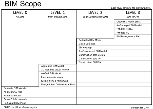


Each level can produce the products of previous levels, although these products may not be required as a deliverable.
Deliverables can be dropped or moved into another level. For example Level 2.5 might be Level 2 plus FM COBie & IFC data, but not As-Surveyed BIM model or iBIM. The idea is to provide a flavour of the scope of BIM required, not an exact measure.

To clarify the different ways what are traditionally called "As-Built" documents of a project can be delivered I have used:

As-Built
Final version of Design Intent documents, including all instructions issued by the design team.

As-Constructed 
As-Built revised to include items not normally present in design intent documents and instructions issued by contractor. May include final versions of shop drawings.

As-Surveyed
A BIM model of the constructed building based on surveys of actual built and  installed elements.

BPB CONTENTS

The BIM Scope level selected will inform what each section of a BPB contains. For a BIM Scope Level 0 some sections may be one sentence, but generally a BPB should include all the following sections.

INTRODUCTION

Describe where the BPB fits into the overall BIM Management Plan (BMP). Refer to my previous post Single project BIM Execution Plan: a good idea? for more information on the structure of a BMP.

REVISIONS

A place to record revisions to the BPB, but also where there is a description of the process to revise, approve, and distribution it.

DEFINITIONS

A very important section. Provide definitions as used in this BPB, not generic industry definitions. Read my post It's OK to not do BIM on an example of the importance of defining what is meant.
For example if the intention is BIM Scope level 1 then BIM in this context may mean BIM for construction only, not the usual definition found in Wikipedia. Alternatively define another term for what you mean. In this example you might use VDC (Virtual Design & Construct) instead of BIM.

OWNER OBJECTIVES

List the outcomes you are expecting from BIM deliverables. Besides being a valuable exercise for the owner to go through, it acts as a control point for all deliverables. Will a deliverable contribute to one of the objectives?

OWNER BIM USES

List the BIM uses deliverables will be used for. Only include specific uses required by the owner to achieve one of their objectives.  For example 4D (programming) is not an owner BIM use, it is a contractor BIM use. 5D (costing) is not an owner's BIM use, it is their cost consultant's BIM use.
If it is considered that other's BIM uses are desirable on the project describe the deliverable you would get from their use. For 4D you might have "3D visualisation of staging to stakeholders". For 5D "costing based on frequent and accurate quantities".

BIM DELIVERABLES

List specific BIM deliverables by the different parties, which may include:
  • Design Team
  • Contractor
  • FM provider
Deliverables from all parties may not be necessary, or there may be others not listed above. It will depend on the BIM Scope and how the project is structured.
Only list BIM deliverables. Other deliverables should be covered elsewhere in other documents. For example delivery of construction drawings is not a BIM deliverable, but deriving construction documents from a BIM model is.

MINIMUM MODELLING REQUIREMENTS

Define expectations of how BIM models will put together. Depending on the BIM Scope, this could be:
General Description
  e.g. model assemblies larger than 100mm (4")
Specific Description
  e.g. All architectural elements built-in, all main structural elements (but not connections),
   all fixed ductwork, all cable trays, all pipework to fall and/or with diameter > 100mm (4"). 
LOD Table
  a simple AIA E203 type table, or full blown USACE M3 type table.
  (refer to my post What is this thing called LOD for a description of LOD tables).

BIM EXECUTION PLAN (BXP) REQUIREMENTS

As described in my post Single project BIM Execution Plan: a good idea? each participant should be required to produce their own BIM plan within the framework of the overall BIM Management Plan.
This section is where the minimum requirements for those plans are set out.
It is important to describe requirements as "minimum", and keep to what is critical. It shouldn't be a place where others are taught how to do a BIM plan. Whilst other BIM guides and standards may be referenced (AEC[UK], USACE, NatSPEC etc), be careful of requiring "compliance" with them. Better to use words like "similar to" or "in general compliance". None are 100% suited to all projects, or structured to suit everyone's needs.
Again the BIM Scope will inform what is required. BIM Scope Level 0 only requires Participant BIM Plans, Level requires a Design Intent Collaboration Plan as well, Level 2 also Construction BIM Plan (refer BIM Scope diagram above).

COMPLIANCE EVIDENCE

Set out processes that check requirements of the BPB are being met.
This may include deliverables like:
  • Statements about how the various BIM Plans meet the objectives of the BPB.
  • Approval processes for the various BIM Plans and their revisions.
  • Audits of BIM models to show minimum modelling requirements are being met.

SPECIFIC INFORMATION

Specific information relevant to the project should be provided as appendices.
For example if the owner is doing their own FM their specific FM requirements, like what data is to be captured and provided, should be supplied as an appendix. If COBie is a deliverable define what fields are required, if IFC what version and what parameters etc.
As appendices they can be updated separately to the overall BPB.

TAKE OWNERSHIP OF YOUR PBP

I apologize for this description being some what generic, but when I attempted a more detailed description it quickly became complicated and unwieldy (like all the published BIM guides).

At the end of the day you have to make your own PBP that is meaningful to yourself and those who will need to rely on it. My experience is that trying to adapt a BIM plan that attempts to cover every eventuality and follow some theoretical "best practice" is more work than just writing down what you know you want.

If you just write something under each of the headings above, no matter how short, that addresses the topic of that heading, you will create a useful BIM Project Brief. Certainly something more useful to a design team, contractor and FM provider than a regurgitated BIM plan based on one of the published guides.


This, and more of my views will be expanded at this year's RTC Australasia conference in Auckland 16th to 18th May, where I'm presenting a talk called "BIM Execution Plans: Avoiding the Noose".


16 March 2013

What BIM should Owners ask for?


There is an assumption in current BIM guides that owners will, and should, direct BIM on a project. But owners are not experts at construction, and not necessarily experts at FM. After all, that is why they employ others to produce their building. But owners have a stake in BIM use. Out of all the participants they are the ones who have the most to gain. So if owners shouldn't get involved in matters they are paying others to do for them, how can they influence the BIM process?

DEFINING WHAT THEY WANT

It is critical that the owner is the one who defines what they want. There is little point getting the lead consultant to do it as a "return brief", or engaging a BIM evangelist (sorry - "Expert") to do one. Owners  need a clear idea of what they want and what they need, because there are costs associated with making BIM demands. It is true there are some benefits they will get for no cost if BIM is used, but they need to know what these are, and which are the ones that will cost.

BIM is actually not a precise term - it means different things to different people (a topic I explored in previous posts What does BIM mean to you? and Its OK not to do BIM). In simple terms there are two versions: BIM as a design and construction process (which I prefer to call VDC - Virtual Design & Construct), and BIM as a facilities management process.
Owners will probably be more interested in the FM BIM, although they may want to use a design and construction team that utilises BIM because they believe they will get a better quality building.

This is where owners need to make their first decision, the options are:
  • I want BIM for facilities management.
  • I want BIM for a better quality building.
  • I want BIM for facilities management and a better quality building.
  • I don't need BIM.

BIM for facilities management

If it is decided to go for BIM for facilities management it is important to be clear about why it is wanted.
Doing it because it is a "good idea", is "future proofing", or "experts recommend it" will not cut it. Asking for BIM that "is suitable for" FM (don't laugh, this is very common) is so imprecise it is highly unlikely anything of practical use will be delivered.

How FM will be delivered must be defined:
  • only raw BIM models provided for future FM use.
  • provided to owner's in-house FM people.
  • provided to owner's FM contractor/consultant.
  • provided as turn-key system by the contractor, including hardware and software.

As-Built BIM model for future works on the project may also be desired. But this is different from FM, as an FM BIM Model is rarely editable. That is, it is very difficult to make changes to its geometry. Data can be changed, like what door lock is on a door, but that door can't be moved in the FM model (and normally you wouldn't want anyone to).
So if a BIM as-built is wanted the BIM model will need to be delivered in an authoring software format, like Revit, Archicad, Bentley etc, as a deliverable in addition to the FM model. If this is not clearly defined CAD as-builts linked to the FM model are likely to be delivered.

A note on IFC. IFC is often recommended to owners as "the" universal future-proof format. But IFC is NOT an authoring format. It is an exchange format that requires authoring software to convert it into their own format. Import an IFC file into Revit and it turns it into a Revit file. And currently very few authoring softwares do a very good job at this conversion, partly because IFC doesn't contain the sort of information that make authoring software efficient to use. Those that claim to do it well are closest to the IFC format - and therefore have the least authoring capabilities. The worst thing you can do is mandate an authoring software solely based on its ability to handle the IFC format.

And a note on COBie, another deliverable being recommended to owners. Construction-Operations Building information exchange (COBie) is standard for communicating information about assets in a building. It only contains data, not a 3D model of the building like IFC. It's usually delivered as a spreadsheet, which can be generated from BIM as well as filled in by human (so information not in BIM can be added), yet be automatically read by FM databases.
Mandating COBie without defining what is required within it will achieve little. It is like ordering a sandwich. If all you ask for is a sandwich, you are likely to get a Vegemite sandwich (but be charged for a caviar sandwich).
If all that is after is information already available for construction COBie requires little additional definition  and is probably the most cost effective way to get FM data delivered.
But an FM system must be capable of making use of COBie data as soon as the project is finished, otherwise that data will be out of date by the time it makes it into the FM system.

BIM for a better quality building

What aspect of better quality is wanted? It is important to keep in mind there may be costs involved, so only those that are actually needed, and there is an appetite to pay for, should be included.

Some areas that might be considered:
  • better understanding of spaces and facilities by stake-holders (through 3D visualization) .
  • better understanding of staging of works (if the project is in stages, e.g. a refit)
  • a range of optimised building performances - thermally, solar, daylight, pedestrian flow, etc.
  • cost control - ongoing measurement for costing.
There is a trap of thinking that forcing the design / construction team to use BIM will automatically result in a better building. More on that below.
Once a list is made it should be reviewed to ensure BIM can actually contribute to better outcomes, and at what likely cost. BIM can do a lot, but not everything.

Don't need BIM.

If  the benefits of BIM are not needed directly by the owner it is still possible to encourage BIM use for construction by requiring evidence the design / construction team are utilizing BIM.
But if  this choice is made it is important to ensure the selection process is able to identifying consultants and contractors experienced and capable of utilizing BIM in their processes. More on that below.

CONSEQUENCES OF OWNER'S CHOICES

What Information is needed?

If it is decided that BIM FM is wanted there needs to be a method to describe what information will be required to be embedded in the BIM model. If FM BIM data is to be delivered to the owner's organisation they must have adequate in-house expertise. There is no point delivering it to the person who works from a room full of filing cabinets and only use the computer to look at porn. If it is to a FM contractor they must be on-board early enough to contribute. At the end of the project it will be too late.

Who provides the Information?

The more information that is wanted the greater the cost. If information required is restricted to information likely to already be in the BIM model (i.e. that is used for construction) the cost may be modest.
But if what is wanted requires more information it is clearly more effort for some-one. If this is the case it is best to consider who is the best party to put that information in. Are the architects the best people to put costing codes in their BIM model for the costing consultant or contractor? Will they know what they are doing? Will they take sufficient care with what they are doing? And will making the consultant team input additional FM data slow them down and so impact on the projects timing? Would it be best to leave it to the FM team at the end of the project?
It is always possible to make some-one contractually obliged to do something, but that does not guarantee the best outcome for the whole project.

Selection Process

Including BIM will make selections processes more complex because an extra requirement has been overlaid. So an owners organisation's manpower demand and time to complete the selection process will increase.
By deciding to use BIM the range of consultant / contractors that can select from may be limited. It may also restrict the range of prices that can be obtained, and it may restrict the range of quality. This trickles down to sub-contractors and trades. If BIM shop drawings are mandated the range of sub-contractors that can be selected from may diminish. As BIM becomes more common this will be less of a problem, but it is important to be aware of it.
Forcing BIM on to consultants / contractors selected on low fees will not magically make them more skilled or competent. And do you really want them to learn BIM on your project? Sounds like a no brainer, but this scenario happens a lot.

Cost & Time

By its nature BIM requires more effort earlier in a project. A developed BIM model is required early in the project to get the most benefit, and it doesn't get put together without some effort. Owners need to appreciate that consultant cash flow requirements will tend to spread towards the beginning of projects. BIM shouldn't make any difference to contractor cash flow, but it might increase the percentage they apportion to preliminaries, particular if they are doing 4D (time scheduling) & 5D (costing).

The time taken by consultants to produce their work may increase, as they are actually doing more. Note, however, that research has shown construction times can be less on BIM projects, so the overall time to completion may not increase.

OWNERS GETTING WHAT THEY WANT

BIM Wash

The first thing is to be wary of BIM Wash. Particularly from academic 'experts' who may try and push processes that have yet to be used, or may even be impossible to achieve. I've experienced an 'expert' employed by a naive client who created a list of requirements that could not be achieved with the software mandated to be used on the project.
Consultants and contractors are also not immune to producing BIM wash. Beware of glossy brochures.

Consultant Selection

BIM can be learned, but beware of inexperience, or experience not relevant. I have seen surveyors claiming they could do an existing conditions BIM model based on their previous experience of importing Rhino models into Revit and calling it BIM.

It is important to pay particular attention to selection of the lead consultant (usually the Architect). A BIM savvy lead consultant can be critical to a successful BIM project.

Collaboration is talked about a lot in BIM circles, and whilst it is somewhat overblown, BIM works best when the consultant team collaborates on creating unified BIM models. It is hard to enforce collaboration, but one way to make it easier to achieve is to select consultants who use the same software. The software doesn't need to be mandated, but it is important to be aware that collaboration will be more difficult if consultants using different software are selected. But that doesn't mean that some-one who doesn't normally use a particular software should be forced to use it for the project. The difficulties they will experience learning to use it will overshadow any collaborative benefits.

It is best to select the project BIM manager from within consultant team, or make the lead consultant  responsible for their selection and management if appointed from outside the project team. BIM Managers are most effective when they work from within the project team, collaboratively, not as an external auditor only responsible to the owner. If oversight is desired a different method should be used (reporting deliverables, milestone issues, auditing, etc). The project team shouldn't be denied an effective manager of BIM processes.

Contractor Selection

Contractors don't so much create BIM as use it.  So their in-house BIM skills are not as critical as consultants. Contractors can always buy in BIM skills, including utilising those of the consultant team. They do however need to appreciate the benefits of BIM and integrate it into their processes.

It is important owners don't try and be a contractor. It is best when selecting contractors to get them to describe their BIM processes, not mandate what they should be. To ensure an effective BIM process let the contractor use processes they believe are worthwhile, and let them explain why they are beneficial. Not all contractors will use BIM the same way, but by getting bidders to explain what they do and why will enable a more effective selection process.

There is currently a tendency to request a separate price to 'do' BIM. My favourite is a hospital in Australia that had a 'BIM option at no additional cost' in its request for tender.  If a contractor is using BIM processes they are doing it for their own benefit.  By separating BIM out it invites costs to be put to processes that would have occurred anyway. I've seen a D & C project where the new owner wanted BIM on the project, so sub-contractors were asked to provide a price to 'do BIM'. Most were already doing it, or at least partly doing it, but of course they still put a price in.
The only reason to request a separate price for 'BIM' is for BIM deliverables that are in addition to what is normally provided for construction purposes, and that are actually required by the owner.

BIM Agreements

I don't intend to go into the nuances of contracts, but obviously it is important BIM expectations and deliverables are included in them.
The Australia AIA has produce a quite good discussion paper on this issue, BIM in Practice L - BIM, Legal & Procurement  (requires free registration), and I've written a response to it in my post A REVIEW: BIM IN PRACTICE - Legal & Procurement

One of the things BIM agreements try and enforce is collaboration. This can be problematic as some interpret collaboration as getting those involved with authoring BIM to put the work of others into the BIM model. Although BIM authors may be best placed to do this, they may not be best placed to take on the responsibility.
If the architect is modelling structural components, there needs to be a mechanism whereby the structural engineer is still responsible for the design of those elements and their correct representation in the model. This becomes critical, for example, if the steel shop drawer is relying on the BIM model to produce their work.

Collaboration is actually not about getting others to do your work, it is about getting others to do things that help you do your work. I explore one example of this in my post Should engineers model accurately?
Collaboration is difficult to mandate, but including clauses on fulfilling reasonable requests from others on the project team might help. But it is still important to ensure that responsibility remains with those with the appropriate expertise.

Is IPD necessary?

In short, No. There is a lot of talk about true BIM not being possible unless Integrated Project Delivery (IPD) type contracts are used. This is simply not true. The advantages of BIM are there for any contractual arrangement.
There may be other reasons you might want to use IPD, but don't do it just because you think the BIM will be better.

The BIM Brief

Critical to owners getting what they want is how it is described to others. What is needed is a clear, consistent method that flows through the whole project from start to finish.
The best way to do this is to integrate owner requirements into a project BIM Management Plan.
But I don't mean a single BIM Execution Plan as advocated by the many current BIM guides. It is unrealistic to expect a single document to encompass all BIM requirements for every participant over the whole life of a project.
What I mean is a series of inter-related documents that together form the Project BIM Management Plan. A topic I explore in my post Single project BIM Execution Plan: a good idea?

The first of which is the BIM Project Brief. This is a document the owner authors and that sets out what their BIM deliverables and BIM expectations are.

A BIM Project Brief (BPB):
  • is a short, high level document.
  • is created before project starts and anyone is appointed (and ideally included in consultancy bid documents).
  • sets out BIM deliverables only, avoids describing how they are to be achieved.
  • describes required content of the other BIM plans that make up the BIM Management Plan.
  • should never need to be revised (unlike some of the other BIM plans).

The BPB should be the only, and guiding, document for BIM requirements on the project. Other documents, like consultant agreements, construction contracts, FM contracts, and BIM plans should refer back to this document.
Because BIM means different things to different people it is not uncommon for a different definition, and therefore intent, to be used in the various contracts and agreements used on a project. The classic is an FM contract that assumes FM data is already in the provided BIM model, but there is no requirement in consultant or contractor agreements to include it.

What does a BPB look like? I've explored it a little in my previous post BIM for Owners: the BIM Project Brief  but I'll flesh it out more in my next post.

I'm also hoping to consolidate my ideas at this years RTC Australasia conference in Auckland 16th to 18th May, where I'm presenting a talk called "BIM Execution Plans: Avoiding the Noose".

01 March 2013

What is this thing called LOD


There still seems to be some confusion about what LOD levels mean, and how they should be used. I must say I have difficulty relating what I do and what I need whenever confronted with filling in an LOD table. If they are this difficult why are we using them? Are they really useful, or just a waste of our time?

HISTORY OF LOD

From what I can gather LOD was developed by Vicosoftware, a software company that produces construction costing software. They saw the advantages of costing straight from a BIM model, but had a problem. How do you tell how accurate, or how definitive, the model elements you are connecting to in the model are? Traditional methods of costing have a human between what was being measured and the way it was being measured. But automatic take off from the BIM model doesn't.
So they developed the concept they call "Level of Detail". A measure of how definitive an element is in terms of costing it. So LOD 100 meant not very definitive, an area or volume rate is accurate enough, LOD 200 you can assume the number of items in the model is correct, but use an estimate for each, LOD 300 items are identified and actual cost can be used, LOD 400 is a measure what has actually been supplied so can be used to assess payments.
Sounds very sensible, very precise. But then the AIA (American Institute of Architects) decided that this system would be a good one to apply to all uses of a BIM model, from energy analysis to 5D programming. They sensibly renamed it "Level of Development" because "Level of Detail" could get confused with the amount of information, rather than the decisiveness of the information. Although both still have an acronym of LOD so the two continue get confused (more on that later).
Others have taken up the concept, and today it has become one of few common BIM concepts that is kind of understood by all  (more on that later).

WHAT EXACTLY IS LEVEL OF DEVELOPMENT

LOD, as in "Level of Development", is a measure of how seriously you take the information represented by a BIM element. It is not necessarily a measure of the amount of information, although obviously there must be enough information to satisfy the LOD level it is at. It is also not a measure of the amount or accuracy of graphical information. The appearance of a BIM element is only one piece of information about that object, and usually the least important. A contractor doesn't need to know what a desk looks like to order it, nor to place it in the building. But they do need to know what the manufacturer and model number is. Others may need to know its dimensions to coordinate with things around it, but they too do not necessarily need to know what it exactly looks like.

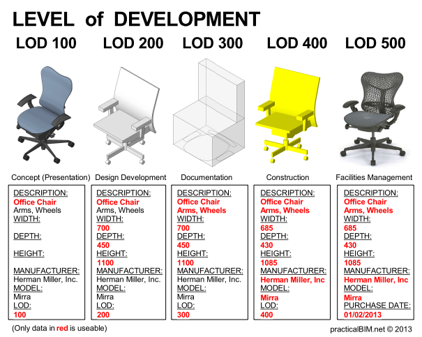
Therefore LOD levels for a chair might go:
LOD 100 = there is a chair
LOD 200 = there is a chair that has nominal space requirement of 500x500
LOD 300 = there is a chair with arm rests and wheels
LOD 400 = manufacturer and model number.
LOD 500 = manufacturer and model number, supplier, date purchased

or in general terms:
LOD 100 = there is a thing
LOD 200 = there is a thing about this size
LOD 300 = there is a thing with these functions and options
LOD 400 = it is this particular thing.
LOD 500 = this particular thing provided by this person on this date.

The purpose of an LOD table is that it tells others what information they CAN USE. To put it another way, it is a measure of the certainty, or confidence, of that information. So even if a chair in the model contains information that would satisfy LOD 400, only the portion of that information that satisfies LOD 100 can be  relied upon with any certainty. This means a chair family from a manufacturer could be used at LOD 100, but everyone knows (by referring to the LOD table) that this particular chair is not necessarily the one that will be actually used.


LOD is also a measure of progress. At LOD 100 there is obviously more work to do to reach LOD 300. In that sense it is like the traditional percentage complete of drawings. Assuming LOD 500 is 100%, then LOD 100 = 20%, LOD 200 = 40%, LOD 300 = 60% etc.
Except LOD contains more information. It tells you how decisive each element is, not just how complete its representation is on a drawing. It is more useful to know that on a plan the floor is 60% complete (LOD 300), the walls are 50% complete (LOD 250) and the service ducts are 40% complete (LOD 200), rather than the whole drawing is 50% complete (the average of all elements).

SO WHAT IS LEVEL OF DETAIL

Level of Detail is a measure of the amount of information provided. Because it is only a measure of quantity, the underlying assumption is that all provided information is relevant to the project and so can be relied upon with certainty.


Because of the confusion between the two LODs, most BIM guides and plans use other terminology for Level of Detail.

Some examples:

CIC (Penn state)
"Information Level of Detail" - AKA "Info"
A - Accurate size & location, including material and object parameters
B - General size & location, including parameter data
C - Schematic size & location

USACE M3
"Grade"
A - 3D + facility data
B - 2D + facility data
C - 2D, part of an assembly or text description

AEC (UK) BIM Protocol
"Graded Component Creation"
G0 - Schematic
G1 - Concept
G2 - Defined
G3 - Rendered

USACE is probably based on the CIC definitions, but customised to suit the current abilities of BIM software and the consultants they use. I suspect it may change over time. The AEC (UK) grades include 'Rendered' which is purely graphical, which seems to suggest it is a measure of graphical detail only. Their accompanying diagram shows 3D representation, although presumably 2D only would be acceptable.

LOD TABLE STRUCTURE

Typical LOD tables are a 2 dimension matrix, down the left side are Model Elements, across the top the first heading is project stage or Project Milestone - (e.g. Concept; Schematic; Documentation; Construction; As Built), below that is LOD, and any other measurable, like MEA (Model Element Author), Grade (Level of Detail) etc.

Some are others loose and flexible (like AIA E-203):


some are incredible long and complicated, (like Australia's NatSPEC):


The most common other addition is "Model Element Author". This is, as the name suggests, the authoring party of an element. Typically this is the structural engineer for structural elements, mechanical engineer for ductwork etc. It has nothing to do with LOD but is useful information as is sets out who does what. My reading is it sets out who is the creator and responsible party in the BIM model, and not necessarily contract deliverables like drawings and schedules. For example the architect may be the MEA of structural elements because the structural engineer won't model accurately enough for the architect's purposes (see my previous post Should Engineers Model Accurately). But of course the structural engineer is still responsible for structural contract documentation for construction.

Other additions include the Level of Detail (AKA Grade or Information), and really anything else that may be useful. In the past I've included method of delivery which provides a timeline for when information gets put into the BIM model.

BUT THEY AREN'T CALLED LOD TABLES

Although I am using the term here there is actually no such thing as an LOD table because LOD is used in tables with other things, and for slightly different purposes. Some of the names for tables include:
Vicosoftware              - "Model Progression Specification"
(US)AIA                     - "Model Element Table"
USACE                      - "Minimum Modelling Matrix" or "M3"
Veteran affairs (US)  - "VA Object Element Matrix"
NatSpec                    - "BIM Object Element Matrix"

So really LOD table is a generic term to describe to tables that include LODs. Is any name better than others? Again I think Vicosoftware got it right. LOD tables may describe other things, but LOD fundamentally describes how information in a BIM model will progress. How much information will be usable at each stage or milestone of the project. They use "Model Progression specification", but "Model Progression Table" or "Model Progression Matrix" are just as good.

DEVELOPMENT or DETAIL - IS THERE A DIFFERENCE?

Level of Development and Level of Detail are closely related. You can't have a certain Level of Development if the Level of Detail doesn't exist.
Only defining the graphical level of detail seems pointless. It doesn't matter how realistic a chair looks, if you don't have the manufacturer and model data no-one can cost or order it. It just looks pretty.

The level of graphical appearance doesn't necessarily progress during a project, it may actually go backwards. The realities of a project usually mean you use the highest Level of Detail at the beginning when there is the lowest Level of Development, as this is when you use rendered images to sell the design to your client and stake-holders.
And to keep the complexity and size of your documentation model low during documentation you want to use a low Level of Detail, even though the Level of Development is quite high.

Of course Level of Detail could explain more than just graphical appearance, but it still doesn't communicate what everyone needs to know - what information can I use with certainty?
And is there any point defining Level of Detail if it is required for Level of Development? Probably not.

To avoid confusion we all should always use the acronym LOD for Level of Development, and use some other term for level of detail. "Grade" is used by a few BIM guides, but it not very descriptive. To keep the metaphor going how about "Depth of Detail" (DOD), where each LOD is a level of certainty passing through the Depth of Detail.


The diagram on the left below shows what is meant when you use Depth of Detail only, the one on the right when you use Level of Development (which by inference includes DOD).


IS THERE A POINT TO LOD?

The original restricted use for Level of Development (LOD) developed by Vicosoftware makes sense, but when you apply it to a cover all uses for BIM information it starts to loose clarity. The reality is LOD levels means different things for different uses, so now you need another table - the BIM Uses table - to explain what uses each LOD level can be used for.

LOD makes sense if you link it with model elements (by putting it in a parameter for example) so your costing software can extract LOD data directly from the model. But when it is listed in a separate document where is the advantage? It seems strange (and not BIM like) to keep LOD requirements in a place separate from where those creating the information that satisfies those requirements are working. Shouldn't it be part of the model accessible to all those working and using the model, not in a separate spreadsheet or word processing document?
Indeed is a better use for LOD one where it describes what level of development (or certainty) an element is after the fact? Users nominate the LOD of elements they are working on as they go. As element information becomes more definitive it's LOD increases. Then LOD would be in the model, and extractable as a schedule.

When first explaining LOD to a director (an architect) his initial response was "you mean LOD is the same as a project stage". My first reaction was "well, yes and no". But when I thought about it, yes it is. By separating LODs into different project stages it is just stating the obvious. Of course at concept stage most things will be at LOD 100, at As-Built Stage LOD 400. There will be some things at different LODs, but is it worth filling in a massive table for these few exceptions?

Which leads to me to my other reservation. Are they serious when they say every model element type has to be listed with it's own author and LOD? And use Uniformat or Omniclass or Masterformat? It is not just the massive amount of work to do it, who will ever refer to it? Do they really think the mechanical engineer is going refer to it to find out if he has to model duct work because some-one else might be going to do it?

Going by the current BIM guides and standards an LOD table is both over complicated and yet imprecise. A lot of effort for little practical benefit. If people just followed the BIM guides and standards there is a real danger LOD tables will be a "tick the box" task. Done once and never referred to again.
But an LOD table could impart some useful information. What is that information and what is it the best way to communicate it?

WHAT AN LOD TABLE IS TRYING TO COMMUNICATE

An LOD table is an attempt to record agreed (whether voluntarily or not) responsibilities around a BIM model.  As mentioned above, it only relates to the BIM model, not other deliverables or responsibilities.

For each part of the BIM model and at each stage of the project we need to know:
  • Who is the author and responsible party.
  • What is in and not in the BIM model.
  • How much of the information embedded can be used with certainty.

Obviously the complexity and amount of detail required for each of these will be different for different types and sized projects. The level of sophistication achievable will also depend on the BIM experience of the project team. So to have a one size fits all approach doesn't make sense.

THE LOD CONCEPT

So should we throw LOD tables out and come up with a better alternative? Many have made the same suggestion and even come up with alternatives. I've seen what used to be LOD tables have LOD removed and replaced by percent complete, because everyone understood what percent complete means. Some have replaced LOD with Depth of Detail (like USACE and AEC(UK)), because that is easier for people to visualise.

But I think LOD is a good idea - as a concept. It holds more information then Depth of Detail or percent complete, but is still a simple concept. I don't think it is a good idea as a 'standard', if applied too rigorously LOD tables quickly become irrelevant, and a management burden on projects.
So, a bit like the definition of BIM (see my previous post What does BIM mean to you?), it is best to treat LOD as a broad concept rather than a precise tool. We all need to understand what it generally means, but still appreciate it means different specific things to different people, and on different projects.

FLEXIBLE LOD TABLES

The (US)AIA E-203 Document uses LOD and MEA (Model Element author) in its Model Element Table. But it is not highly prescriptive about how that table might be constructed. Although Uniformat is suggested, it is not compulsory  ". . . there is no single best system for classification of the Model content.", and "the user is also free to delete or alter the CSI structure and insert another guideline or a firm specific or project specific model element structure."

The structure of LOD numbering, broad definitions 100 apart, leaves plenty of scope to slot in extra numbers with special meanings for your project. I've used 250 and 350 before to overcome issues around services construction design being done by D & C contractors.

The (US)AIA E-203 is also not strict on LOD use itself, suggesting items not modelled be identified as "NM". This could be expanded to code where the information can be found.
And just to make it really flexible the Model Element Table has a notes column for each stage plus a notes column for each model element.

I believe the (US)AIA approach is the right one. Use the broad structure and concept, but tailor it for your own purposes.

HOW TO MAKE LOD USEFUL

The best way to make LOD useful is to think about how you can make LOD meaningful to your project and the project team, or your office if you are the BIM manager.

If you are required to do an LOD table say you will comply the (US)AIA E203 document, rather than one of the other BIM guides. It gives you pretty much the freedom to create an LOD table any way you like.

Don't be afraid of doing a really simple LOD table, particularly if it is your first one. If the project team is using Revit there is no reason you couldn't list Revit categories as your building elements. If you are comfortable listing trade packages, do that.

Create your own LOD levels. That's why the standard ones are so far apart, it is designed to have other, in between levels. Just make sure you define what those levels mean.

Do multiple LOD tables if it helps. I do a simple short one for sign off by directors, owners and sometimes the contractor, and then a more elaborate one (which aligns with the simple one) for the project team. By taking this approach you could, for example, make the AIA E-203 Model Element Table simple, so that it only sets broad requirements (and therefore flexible, always a good idea when signing a contract), yet still have the opportunity to be more precise when managing the project team via a more detailed table.

And finally think of other uses for LOD. Remember, it is a concept, not a rule. Why not have an LOD parameter for objects in your model to track progress and work as a QA check?
For example:
- LOD 290 = preliminary construction defined;
- LOD 292 = checked for functional requirements;
- LOD 294 = checked for fire requirements;
- LOD 296 = checked for smoke requirements;
- LOD 298 = checked for acoustic requirements;
- LOD 300 = final construction defined;


Let's take ownership of LOD and make it our own.

Postscript:
A discussion on the [US]AIA E203 document LOD defintions can be found in my post
 LOD, are we there yet.


Bored with BIM?
Need a present for that special woman in your life?
The Lost Woman series follows the adventures of Christina as she makes her way through a world of design, fashion and ... men.
Book one of the series, "Awakening the lost woman", is available now on Amazon,  Google Books,  Kobo  and  iBooks.

15 February 2013

Can BIM alone be used for Construction?


BIM is promoted as the future, the 'new way of doing things'. There is an assumption by BIM evangelists that the BIM model will be the receptacle of all information about a building, making drawings redundant. But is this really true? Is it even possible?

TRADITIONAL PRACTICE

For a contractor to build a building they need to know what they are building. The various sub-contractors and individual trades need enough information to first price their work, then to do their work. But these people do not just follow a set of instructions, they bring their own expertise. The vast majority of building trades require years of training, they are experts in their own right.
So what information do they need? They need to know the Design Intent of what they are doing. They need just enough information to provide a framework, working out the rest themselves. Provide any more information and it is likely the results will be sub-optimal and inefficient.

Current practice is to provide this information as drawings, schedules and specifications. Only relevant information is provided in these documents. If the location of something is not critical it is not dimensioned. If something has to be provided that complies with a description it is not necessarily included in drawings or schedules. If something is included in a schedule, it may not be included in drawings. Therefore, although these documents have never been a full description of the building, they are adequate to build it.

ENTER THE BIM MODEL

With a BIM model the building has to be completely modelled. You can't leave out a facade just because it is part of a design construct contract, you have to model something. And if something is in a schedule it has to be in the model. Unless every screw, bolt, flashing, seal etc. is modelled in 3D it is not possible to explain how things go together like a drawn detail does.
But most importantly, how do you explain Design Intent when all you can do is create a virtual object? How do you explain which attributes of the virtual object are critical, important, for guidance, or don't matter at all? For example every object has a precise location in the model, yet the precise location may not be important, and may actually be unpredictable because it depend on decisions that can only be made on site.

LOD (Level of Development) tables are an attempt to overcome this shortcoming. But they are not really up to the task. On the one hand an LOD table is not precise enough (how do you use an LOD table to explain that the height of (some) power outlets are critical, but the location along walls is not?). On the other hand, even with this cut down amount of information, LOD tables are becoming far too detailed and complex to be of practical use. The number of element types in a building run into the thousands, let alone the number of actual objects. To assign a LOD to every one, and then track that it is being followed in the model, for each stage of a project, is just not practical in the real world.

BIM TECHNOLOGY

None of this should be a surprise to those that work in the AEC industry. Certainly the authors of BIM software are aware of it.
Take Revit as an example. The model is displayed to us via 'views'. We then add notes, dimensions and other annotation to explain our intent. These views are then placed on sheets that can be printed to paper of electronic format (DWF, PDF etc), and exported as 2D CAD files. Revit utilizes traditional practice to solve the problem of communicating design intent.

Bentley are going a step further. They have an initiative called 'Hypermodel' (as in Hypertext) that shows references to other drawings and documents in the 3D model. It is not so much a method of providing design intent information in a BIM model, more like a hybrid solution, providing access to traditional means of communication directly from within a 3D model (as opposed to just from views, as Revit does).

To go back to the original question - is it possible that BIM models will replace drawings - the answer is yes and no.  Yes BIM models will one day be able to communicate design intent, but no, they won't be BIM models as we know them now. There will have to be some sort of added technology. And it is not just a technological problem. If every BIM software vendor has a different approach we will be no better off. It is not realistic to expect contractors and trades people to be familiar with a whole range of software products just to get the information they need to build a building. There has to be some kind of commonality - like drawings, schedules and specifications.
There are probably technologies out there that could do the job now, but with nothing definitive in sight I would say for the foreseeable future it will still be drawings, schedules and specifications. So what does that mean for the BIM models we do now?

SO WHAT IS A BIM MODEL?

Another way to look at it is to define a BIM model as something that is not intended, by itself, to communicate design intent or how to construct the building.
Rob Snyder, who is involved in Bentley's Hypermodel initiative, has succinctly defined the problem. To him the BIM model is the 'environment'. But this environment is not meaningful unless there are 'statements' about it. For example a drawing with notes, dimensions, details is a 'statement'. It only shows the portion of the 'environment' that is relevant, with added 'statements' to point out things that need to be communicated.

So a BIM model is not another way of documenting a building project. It can not communicate in it's own right. It's purpose is as a resource to create deliverables. To create construction documentation, to run structural, thermal and other analysis, to participate in FM, and a whole range other other uses.

PRACTICAL CONSEQUENCES

By treating a BIM model as a thing in itself confusion is avoided about where information that can be used to construct the building resides. This also clarifies where your contract documentation deliverables can be found.

That said, a BIM model may well be a client deliverable, but make it clear it is only provided as a resource for others to produce their deliverables. So by all means provide your BIM model to others outside the design team, but strip out all traces of documentation - views, sheets, schedules.
You can do this very quickly in Revit:
  1. Create a 3D view only showing what you want to export.
  2. Place that view of a sheet.
  3. Find the sheet in the Project Browser, right click on it, select "Save as file...".
Keep the view and sheet and next time you only have to do step 3.

And make sure project BIM plans are only be about the BIM model. List documentation (production of drawings & schedules) as a BIM Use, but don't include anything about drafting standards or drawing production. These can be referenced in the BIM Plan, but should be completely separate documents.


So don't treat your BIM model as part of your documentation deliverable, and be clear to everyone, from your boss & colleagues to clients, contractors and trades, of this fact.

01 February 2013

Real Collaboration - Working with Engineers


From comments I have garnered it seems the consensus is that engineers will have to model accurately for BIM to work. There was a lot of talk about the many issues that will need to be resolved, work practices that must change, and fees that need realignment, but no alternative strategy to create true BIM materialised.

In my previous post, Should engineers model accurately, Method 4 - Engineers Model Accurately was the only one that received any support, or even serious consideration.

The most common objection (from engineers) to modelling accurately was that "their fee didn't cover it", or "there isn't enough time", which is the same thing. This may well be true, but upon what basis do you ask for increased fees? One of the benefits of BIM, and in particular accurate BIM, is clash detection and avoidance. But can you really go to your client and say "pay me more and I'll reduce clashes between my designed elements and the rest of the building". What do you think they will say? They believe they are already paying you to ensure there are no clashes. As one commenter pointed out, the A/E industry has been getting away with not providing what they promise - fully coordinated design - for years.

Another common objection, was that using BIM software like Revit is more work than traditional CAD. This is just not true.
Whilst you do things in BIM software you don't do in CAD software, there are more things you don't have to do in BIM software that you do have to do in CAD software. As an example, at the request of the contractor we changed the names of some levels. In Revit this took less than a minute, just a simple text edit in one place. When we told the structural drafter, who is using CAD, he groaned as he now has to find, open, and edit every CAD file where these levels are referenced. I'm dreading telling him we are changing door frame sizes to doors in concrete walls. One parameter change for us, hours of stretching lines and redoing dimensions for him. Properly used (i.e. in the way it is designed to be used) Revit will decrease your workload. You won't get far arguing you should be paid more because your BIM software is harder or more time consuming to use (although you might get paid more if you are one of the few who can use it well).

And I can't avoid mentioning the recurring complaint about architects continually changing the design, which apparently is the bane of every engineer's working life and profit margin. Of course the cause of this really has nothing to do with BIM, or does it?
The name Revit is a portmanteau of 'Revise' and 'it'. It's original creators recognised that designing a building is a process of making changes, to optimize the building's design. And that a product that made making changes more efficient had a market. It was only later, after AutoDesk bought it, that the BIM idea took over. So Revit is software designed for making changes easy. And it does. Change one parameter and you can change the size of say, a door, across the BIM model and all drawings and schedules those doors appear in. Even dimensions on drawings change.
So architects using Revit may indeed be making changes to their model that are more vast, and doing it more often, than when they used CAD. Because they can, and because the job of architects is to optimize the design.
Revit Structure and MEP are Revit Architecture with some extra bits added. It is fundamentally the same software. So if engineers used Revit the same way architects do, they wouldn't have such a problem with design changes. They too could use their software to make vast and frequent changes with little extra work.
And who knows, they might also be able to do a better job, by optimizing the building's structural or services design. With the added bonus of annoying the architect with frequent changes!

What does Model Accurately mean?

Before continuing I just want to clarify some things that some commenters were confused about.
By accuracy I mean elements being represented as geometrically accurate 3D representations at their actual location, rather than symbolic representations. They don't need to be realistic (it is best if they aren't), but they do have to represent their spatial requirements.
What I don't mean is sloppy work, where the intention is to place it accurately but that hasn't happened. All AEC consultants can be guilty of this.
Elements need to be spatially accurate during the design process, not just at the end when construction commences. How else can the architect develop the design so services fit? It amazes me when engineers think they can come in at the end of a design they have had no meaningful input in to and expect their services to fit. Or expect the owner to finance an oversized building just so their services will easily fit and make their job easier.
Another clarification is that no-one expects (except BIM evangelists) every single element to be modelled accurately. As architects and engineers we are doing design intent, not a 100% virtual representation of the finished facility. Elements that are large and have specific spatial or location requirements, like ducts, plumbing pipes to falls, light fixtures, large cable trays, do need to be modelled accurately. But elements that are small and can run anywhere, like supply pipes and cabling, don't require as much accuracy. Some elements fall in between. For example power outlets might have a required height, but the exact location along the wall is not critical. So it is not necessary to model all wall studs just so power outlets can be located to avoid them.

In a practical sense, what can be done?

But it is not my intention to beat up on engineers. I feel their pain. Whilst engineers may not be able to argue for more fees, the reality is their fees probably are too low. In a free market fees paid are based on actual work performed, not what is promised or even should, in theory, be done. The other reality is this is not going to go away. Not all engineers have been forced into BIM projects yet, but eventually it will happen.

VALUE ADD
Whilst no-one can claim extra fees for better coordination, offering to provide evidence of coordination could be construed as an additional service. By evidence I mean actual clash reports, rather than just the promise that there will be no clashes. Another potential extra is providing IFC models. Both of these would involve additional work (and possibly software) to just to deliver, but the potential is there to value add. There may be other opportunities, properly used BIM software can leverage a lot of down-stream processes.

BE MORE EFFICIENT
Utilize your BIM software to improve your work practices and work flows. Unlike CAD, which is just a generic drawing package, BIM software is designed with your workflows in mind. For example Revit MEP and Revit Structure are designed to link into analysis software. Revit has a workflow for monitoring changes in linked models (like the Architect's model) called Copy/Monitor. Some commenters reported a lot of success with Copy/Monitor. Some complained it was 'too hard', but I suspect those people weren't committed to making it work. Don't fight your BIM software, use it to its full advantage.

TAKE ADVANTAGE OF COLLABORATION
There is an expectation that BIM will involve collaboration. If a client mandates BIM, you can bet they assume collaboration will occur. But what does that mean on the ground? As I have said elsewhere, my definition of collaboration is mutually beneficial cooperation. You scratch my back, and I'll scratch yours.
If the architects say they want you to accurately place power outlets, ask them to do something in return for you. I hear a lot of bitching from engineers about being dudded by architects, but when I ask them what I can do to help (as the architect) I don't get a definitive request to do anything specific, just more bitching. So don't be afraid of asking, but make sure you are explicit about what you want. Just asking the architect to not keep changing the design is not going to do you any good.

Some suggestions (from a non-engineer):
  • Get some commitment that the architects model will be to a certain quality:
    - existing elements will be edited rather then deleted and remade.
    - objects hosted to level or floor rather than wall, floors or ceilings.
    - each ceiling has its own level.
    and make sure to let them know if they don't keep these commitments.
  • Ask the architect to set up views in their model that you can use. If they won't do it ask if you can come into their office and set them up in their model. Might save you from having to recreate views every time you get an updated model. 
  • Ask the architect to use your families. Or at least start of with your families, it probably doesn't matter if they change a family's appearance as long as all the connectors and your parameters are still there.
I'm sure there are many others engineers have dear to their hearts. Don't be afraid to ask. If you face resistance remind them of their duty to collaborate. Offer to do things that help them. Remember it is all about cooperation and negotiation.


So for all you struggling engineers out there, there is hope. Admittedly there is the hurdle of learning your BIM software, but once through that (and it does end), there are practical things you can do to lessen your load to compensate for having to model accurately.

18 January 2013

Should Engineers model accurately?


Here in Australia (I assume it is the similar elsewhere) engineers (M, E, P, and Structural) are responsible for specifying what things are and how many there are, but the architect is responsible for location. So traditionally engineers only need to show their objects schematically, whilst the architect has to show those same objects (or at least the ones that are visible) at their actual size and exact location so they can be dimensioned.
Examples include structural elements (like columns) on setout plans, A/C register and lights on ceiling plans, electric and data outlet on wall elevations, plumbing fixture locations on plans and elevations.

The theory behind BIM tells us that we shouldn't have duplicates of elements in the model. Besides waiting for the nirvana of Integrated Project Delivery (IPD) and the single BIM model how do we deal with this problem in a practical way?


METHOD 1:
Only objects authored by the architect are official BIM information.
Elements may be duplicated but only the architect's version is used for BIM. Effectively the architect becomes a drafting service for other consultants on the project.
Problems:
  • architects would have to duplicate all engineer designed objects, even ones not relevant to design intent (like ducts above ceilings, plant, switchboards etc).
  • all engineering data accompanying these elements would also have to be duplicated within those elements.
  • the benefits of engineers using BIM software for analysis diminishes if there is no need for them to author BIM data.
  • adds significant extra work and legal liability for architects, a liability possibly not covered by PI insurance. 
Summary:
Probably the reality on many current projects where engineers haven't taken up BIM, but not desirable into the future.
In theory possible on large IPD projects where BIM authoring for everyone is by a third party (the project BIM author?), but not a practical solution on the vast majority of building projects.


METHOD 2:
The architect can move objects authored by engineers.
The engineers accurately model their elements but the architect has the ability (and authority) to move those elements.
Problems:
  • not possible with current BIM authoring softwares.
  • moving engineer's elements may affect the engineering design. For example moving a column may increase a beam span.
  • moving engineer's elements may break the setup for analysis. Moving a ceiling register may disconnect it from the thermal analysis system.
Summary:
Maybe technically possible if software written to do it. Solves the architects problem, but adds to the engineers problems. The architect being able to make changes to engineers elements would be a legal minefield.
A hybrid could be a workflow that allows the architect to move objects in a copy of the engineer's BIM, that is then used by the engineers, after their review, to move their actual objects.


METHOD 3:
Elements are duplicated by different authors,
each version can only be used for specific purposes.

Each engineer authored element is flagged as only usable for scheduling, and each architect authored element flagged as only usable for location.
Problems:
  • still duplicate elements in a BIM model.
  • not practical, or even possible, with all current BIM authoring and reviewing softwares.
  • introduces risk of wrong information being used. An LOD table buried in a BIM Execution plan is not going to stop an electrical apprentice using the wrong information.
Summary:
The reality on projects where Revit is used with no BIM requirements.
Technically possible if BIM software written to accommodate it. May also be possible within some BIM federating software with an appropriate setup/workflow.


METHOD 4:
Engineers model accurately.
Engineer authored elements are both geometrically accurate and placed accurately.
Problems:
  • Additional modelling (drafting) work beyond current practice for engineering offices.
  • greater co-ordination required as architects still have to instruct engineers where to place these  elements.
  • potential program delays if engineers don't keep up with architect's design (particularly for distributed BIM like Revit).
  • allied workflow issues - do engineers also provide BIM for the architect's design options and design studies or do architects duplicate engineer's elements for these?
Summary:
If engineers say they are doing BIM, or are required to by their agreements, this is (according to BIM theory) what they should be doing.
On the face of it engineers would be required to provide more than they have in the past - accurate 3D model rather than 2D schematic. But is it actually that much more work with BIM software like Revit? And is this extra compensated by the benefits of having an accurate BIM for other engineering uses like scheduling, analysis and clash detection?
However more effort is definitely required in the workflow of ensuring engineer's elements are placed accurately where the architect wants them. Is this effect of what the BIM evangelists mean when they talk about "collaboration"?


METHOD 5:
Sub-contractors do accurate BIM.
Sub-contractors provide shop drawings as accurately located and sized BIM. Engineers just provide schematic information.
Problems:
  • during design phase effectively the same as METHOD 1. The architect will have to model all engineer's elements to create a useful BIM.
  • BIM can't be used for analysis or clash detection before construction starts.
  • a lot of design work won't be able to be finalised until construction is under way, leading to possible delays in completion.
  • in current practice not all engineer's elements are shop drawn. Power & data outlets, ceiling fixtures are some examples that are not.
Summary:
This method often occurs by default in Design & Construct projects. It is workable, but defeats the purpose of building a complete virtual building before construction, one of the benefits of BIM.
It is also a method advocated by IPD; engage contractor and sub-contractors during design phase so they can contribute. Besides the issues that early selection and engagement of this group entails, it relegates engineers to the role, at best, of advisor, at worst, no involvement at all.

CURRENT SITUATION

This problem can not be unknown to the software developers. Revit's solution is a 'copy/monitor' functionality. Objects between different discipline Revit models can be copied, and then monitored for changes. So this is a type of METHOD 3; Elements are duplicated by different authors but each version can only be used for specific purposes. But it is only a partial solution. There is no direct way to allocate duplicate objects to different purposes in an aggregated or federated BIM model. The other problem with it is the sheer amount of data. For example it is not practical in Revit to monitor thousands of electrical and data outlets or ceiling fixtures found in even moderately sized projects.
Another issue is that a lot of engineers don't see the benefit of BIM to them. I believe one of the reasons for this is due to the slow take up of BIM for analysis by engineers. One of the drivers behind developing BIM for Revit structure and MEP was to use the same model to communicate a design and to perform the various analyses required to inform that design. You would think the advantage of not having to create a new model for every different analysis would drive BIM within engineering offices. But the reverse seems to have happened. Most see Revit as another model they have to do in addition to their analysis models, and treat that model as a drafting tool for doing drawings - schematic drawings.  

I've been involved with projects where all methods but METHOD 2 have been used. It generally depends on how BIM proficient the engineers are and what their client service agreements stipulate. Because, at least in Australia, the client engages engineers rather than the architect, the architect has no power to dictate what they do so we just have to go with the flow.
So no method is ideal, but which one should we strive for?

WHICH METHOD IS LEAST WORST?

Firstly I'd like to emphasise that the list above is not exhaustive. I'm sure others have alternatives they have thought of and possibly used. The other point is that there may not be one method for all situations and projects. But it would be nice if there was.

A word about METHOD 5. It is the one advocated by BIM evangelists. But it fundamentally changes the type of service a consulting  engineering firm provides. Perhaps the work lost to sub-contractors could be picked up by working for those sub-contractors, but it still diminishes the role of engineering consultants. Read my view on the effects of IPD on architects in my post Integrated Project Delivery: Bad News for Architects?

As an architect I'm torn between METHODs 3 & 4. METHOD 3 allows me to hurtle forward doing my work without having rely on other offices, but METHOD 4 ensures BIM data is properly coordinated. METHOD 3 means I have to ensure my duplication work matches the engineers, METHOD 4 means I have to ensure the engineers work arrives in a timely manner.
On balance I think I prefer METHOD 4. It is the proper way to do BIM. Unless I can get that hybrid of METHOD 2 working.

What do you think?


04 January 2013

It's OK to not do BIM


In my last post I made the accusation that the term BIM had been hijacked. After reading the comments in the LinkedIn posts I created, (see BIM confusion in BIM Experts group) I have to admit that the hijackers have got away with it. Besides the usual BIM evangelists reiterating their definition of BIM, comments from real users showed acceptance that the meaning of BIM has changed. It seems consensus is now that BIM describes the whole process, not just authoring processes.

I'm OK with that. My aim is to promote practical BIM, and if it is practical to accept a new meaning of BIM I'll go with it.

But if BIM means all BIM processes, then no-one could possibly be doing all of it. Which means no-one is actually doing BIM. So what name should we use to describe the BIM process each of us is doing?

Virtual Modelling

The term Virtual Design & Construct (VDC) is mentioned in the Wikipedia entry for BIM.  I read VDC as meaning BIM for the design and construction phase of a facility, separate from life cycle, facilities management and other BIM uses.
I find this term attractive because it includes an under emphasized aspect of BIM, a description of the technology, virtual modelling.
VDC sounds more like a process, which makes it clearer. One of the problems with BIM is that it can (and is) read in two ways, a process - Building Information Modelling, and as a thing - a Building Information Model. (hence the redundant term BIM model). To add further confusion there are those that propose BIM should stand for Building Information Management, or the real die-hards, Building Information Modelling/Management (BIMM).
But is VDC precise enough? If you are an architect or engineer VDC is not that definitive because you are doing the design part, not the construction part. And are you doing a process, or are you part of a process?

This is not new, so I don't claim authorship, but I propose the terms Virtual Design Model (VDM) for architects and engineers and Virtual Construction Model (VCM) for contractors and shop detailers. All of who are using a Virtual Design Construct (VDC) process.
Bring in a Virtual Life-cycle Model (VLM) , a Virtual Facility Management Model (VFM) and other V_M participants, then you have a Building Information Modelling (BIM) process.

But where is the Building Information Model? What is a Building Information Model if BIM covers all processes? Could it really literally be one humongous computer file containing everything ever done about a facility? Although technically possible in theory (and one of the fantasies of BIM evangelists), in practical terms not a reality. Therefore BIM, as in a Building Information Model, is a theoretical construct, not an actual physical thing; the name we use when all the different Virtual models created for a facility are talked about as a singular concept.

Why is a clear definition Important?

Having a clear description is important to describe to others what you do, and just as importantly, what you do not do. One our current problems is that when you say you do BIM to someone, they assume you are doing what THEY think BIM is. And as BIM now means all of BIM, you shouldn't be surprised, you haven't been precise enough.

I suggest you tell them:

We don't do BIM, we do VDM (or any of the other V_Ms).

and if you want to sweeten the deal:

Others may use our VDM for BIM, and we'll do our best to make it as easy as possible for them within the limits of the software we use.